The following items are for sale. All in good, working condition.
MFJ Cub 17m. £50+post
Bought secondhand as a built, working unit. I intended to use the rig for SOTA, but then got MTR-5B. Working, good condition, slight blemish to case top, front, above MFJ logo (see picture).
Small Wonder Labs SW-40+ £65+post
40m SW+ QRP CW transceiver with Chinese LED frequency counter and N0XAS PicoKeyer w/ speed pot.
Acquired as a built kit, originally built in the USA. Re-boxed, frequency counter and PicoKeyer IC added, by me. Intended for use as a camping rig with Elecraft style logbook lamp toggled by push switch on rear. In working condition, last used by me for SOTA 20th Anniversary celebrations.
Small Wonder Labs SW-20+ with N0XAS PicoKeyer and Small Wonder Labs Freq-Mite. £SOLD
Small Wonder Labs SW-20+ QRP CW rig built by me in home brew PCB stock case. Silver paint has bubbled in places (see pictures) but could be re-sprayed in silver paint with little effort. Black paint on case top applied professionally and extremely smart. Works fine, however in the spirit of full disclosure, the Freq-Mite and PicoKeyer fire up at the same time and both have Morse announcements at start up, which conflict. Doesn't affect operation of the rig, it's just a racket when first powering up! (I guess a switch could be added to power up one of the devices separately.)
QRP Labs QCX 50w Amplifier with case £SOLD
QRP Labs QCX 50w Amplifier built by me for 20m. In good, working condition. I don't have an accurate QRO power meter, but amplifier puts out in region of 35 watts on 20v supply when driven by my QCX-20. Used the amplifier a number of times for SOTA, it's great for working DX. Could be used with other rigs besides QCX but would need some means of TX/RX switching (+5V PTT needed to put amp into TX).
LNR Precision MTR-3B original version. £SOLD
LNR Precision MTR-3B in very good condition. Unmodified with original phono socket. These rigs originally had a TX fault caused by a manufacturing error, this rig has had the fault corrected by me (capacitor swap) and a full alignment. Rig works flawlessly now - probably the best MTR-3B offered for sale.
LNR Precision MTR-3B LCD £SOLD
LNR Precision MTR-3B LCD in very good working condition.
Steve KD1JV announced that his kit for 2015 would be a five band version of the MTR and this time it would include an LCD. I'd missed out on the three band MTR kit, but I was going to do all I could to get my hands on a five band version! Steve restricted ordering of the MTR-5B to the USA only, I can understand the reasoning behind his decision, as filling in overseas paperwork for every single shipment would be very tedious. It was a bit frustrating, but as least ordering was first come, first served like before. Thankfully I found a kind ham based in NY State to help me out and MTR-5B kit #70 of 98 kits was soon in my hands! The MTR-5B specs from the build instructions -
Switch selected 40/30/20/17/15 meter bands (no band modules to lose or change out) Wide operating voltage range, 6 to 12 volts 15 ma Rx current at 12V supply Efficient transmitter. Low current with 4W output LCD display Push button or Optional rotary tuning 24 hour clock built in, with battery back up Three 63 character programmable message memories Message beacon mode with adjustable pause time Small size: can fit into a 4” x 3” x 3/4” box
The build was fairly straight forward but there were a few issues that had been flagged up by other builders before I had started my kit. It turned out that the supplied reference oscillator was not suitable, so Steve sent new oscillators out via mail. The replacement oscillator caused a slight increase in current consumption, so the rig does not quite meet the 15mA quoted in the specs. The original firmware was found to have some bugs, so replacement firmware was deposited in the AT Sprint Yahoo Group (now ATSprint@groups.io) files area, in order that builders could update the firmware via a TI Launchpad. The new firmware was self executing, so updating the rig was as easy as connecting up the correct wires to the interface and double clicking a file on the computer.
MTR-5B during build. A number of through-hole parts still need adding.
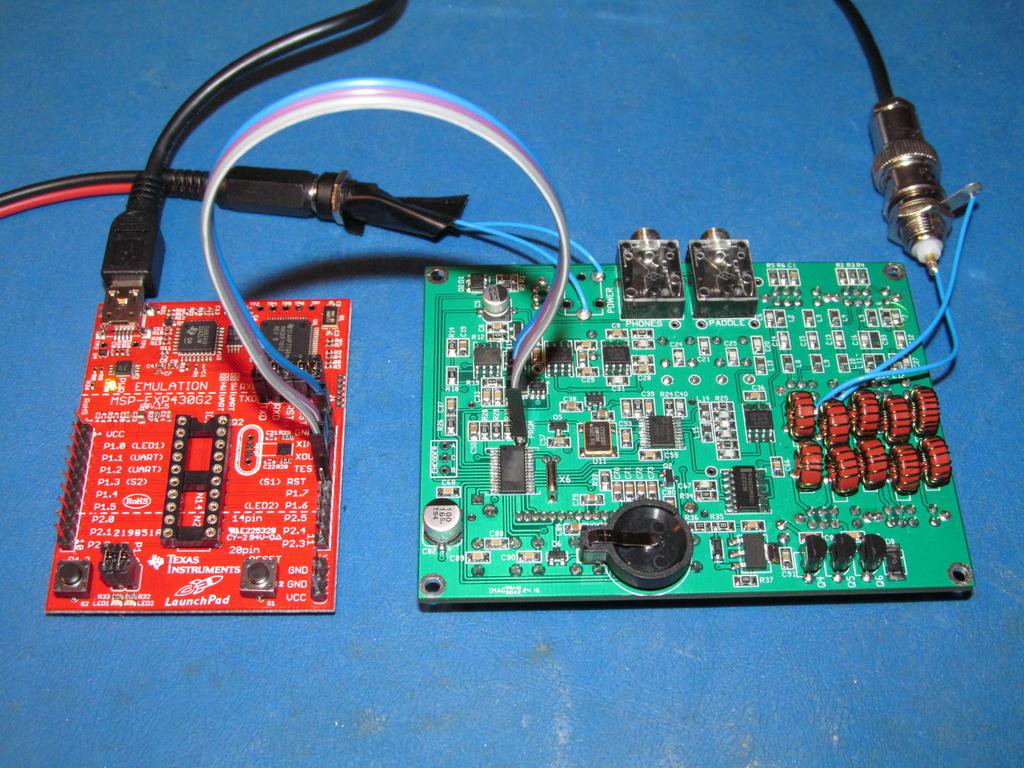
Reflashing firmware with TI LaunchPad Development board
Case made from sheet aluminuim and sprayed with primer
MTR-070 just prior to final assembly
This was an article that I wrote for SPRAT -
KD1JV Designs MTR-5B
Colin Evans, M1BUU colin.evans2@gmail.com
I
discovered Steve Weber KD1JV’s rigs a few years ago. I built the first version
Mountain Topper CW rig (AKA ‘MTR’) in 2012, it was a two band model supplied
without a case. I housed my kit in an Altoids tin and selected the 40m and 20m
bands. I liked the rig so much, that, when the second version was released, I
opted to buy another, this time building for 30m and 20m bands!
KD1JV’s kit for 2015 was the
fourth in the MTR series, called the MTR-5B. The rig now includes operation on
five bands, a backlit four line LCD and optional rotary encoder.
The
MTR-5B kit was a limited run of just under 100, all with a serial number. My
kit has serial number 070. The kit was supplied as a board plus parts,
including solder and connectors, but minus an enclosure. The components are
almost entirely SMD, 0805 size for most resistors and capacitors. The hardest
part of the build was probably mounting the processor and DDS chips as these
are TSSOP devices (Thin-shrink small outline package).
The
build went smoothly and the rig fired up first time without any troubleshooting.
There had been a few issues with original firmware, so I knew, even before
having the kit in my hands, that an update would be needed. Updating the
firmware for the MTR series has been made very easy for us. The MTR series rigs
use the TI MSP430 family of processors, the development tool / interface for
these chips is called LaunchPad, and costs around £10 delivered to your door. To
update the firmware, I simply had to connect three wires from the LaunchPad to
the three programming pads provided on the MTR PCB, then it was a just a matter
of double clicking the correct file downloaded in a .zip folder. Job Done!
I
made my own enclosure from a piece of aluminium sheet ordered from EBay. I hadn’t
tried making my own cases before, I wish I had tried it sooner! Using a vice
that I made at college, it was easy to bend the aluminium sheet into the shape
I wanted. I copied the case style of previous versions of MTR but I sprayed my
rig bright orange as it’s my 3yr old son’s favourite colour (might also prevent
me leaving it behind after a SOTA activation!). I opted to leave off the
optional rotary encoder to make the radio as small as possible, and I also
saved around 10 grams in weight.
The
MTR-5B is a pleasure to use, the receiver is very quiet, by that I mean that
there is very little audio chain noise. There is no volume control, the AF
level is simply limited above a certain point. The sidetone, although generated
by the processor, is very smooth as it is injected before the final AF stage
and is subsequently filtered. The band switching can take a bit of getting used
to as it uses a combination of six slide switches, however previous versions of
MTR have used this system and I don’t have a problem with it. The most
impressive feature of this rig, despite the permanently backlit display, is
it’s extremely low current consumption. Another feature which I really like is
the real time clock, the clock is surprisingly accurate and I find it very
useful for SOTA logging, it will be especially useful to keep set to UTC when
summer time comes along. The clock is kept running by a small button cell when
the rig is not connected to an external supply.
Some
statistics for MTR-5B s/n#070
160g
(5.6oz)
106mm
x 82mm x 30mm (~4.25” x 3.25” x 1.25”) excluding protrusions.
Built
in Iambic (B) keyer with three 63 character programmable messages
Single
conversion superhet, ~500Hz bandwidth
High
efficiency transmitter using 3 off TO92 BS170
4
line backlit LCD with frequency, RIT, battery voltage, time display.
Full
coverage of 40m/30m/20m/17m and 15m. (Option for 80m in any one of slots)
Operating
voltage range 6 to 12 Volts, nominal 9V
BAND
RX mA 9V
RX mA 12V
TX mA 9V
TX mA
12V
Power W
9V
Power W 12V
40m
23.5
18.6
440
580
2.82
4.90
30m
23.7
18.8
490
660
3.06
5.33
20m
23.8
18.8
530
700
3.15
5.40
17m
23.9
18.9
530
690
3.06
5.26
15m
23.9
18.9
620
800
3.12
5.13
Notes
-
RX
current measured with no signal present so will be higher in actual use.
TX
power measured using 4SQRP QRPometer, in turn compared with Nissei RX-203.
A
supply voltage of 7.3V gives approximately 2 watts output on each band.
TX
power output and efficiency is influenced by the spacing of turns (inductance)
on the low pass filter toroids, I just spaced mine neatly and didn’t mess
around too much.
Thanks
go to Steve KD1JV for designing and supplying such a great QRP kit!
I've had my MTR-5B for about 5 years now and it has been, and is, a superb radio. I've only had a couple of incidents where the rig froze, cycling the power took care of those, other than that the rig has been totally reliable and never needed any repair. I use my MTR-5B more than any other radio I've owned, it just does exactly what I want.
I was listening to the SolderSmoke podcast
and Bill, N2CQR, the host was talking about his 'BITX' radio. 'BITX' is
a design by VU2ESE of India, it uses the same basic amplifier block throughout,
and uses a 'bidirectional' architecture. A lot of the circuit is shared
between RX and TX. The beauty and appeal of the BITX design is that it
uses very common (cheap!) parts and there's lot of troubleshooting
information available at the BITX Yahoo group.
The BITX design appealed to me, because, for the last few years, I've had the desire to have a transatlantic QSO with a home made radio via voice. I haven't actually managed a contact to North America with a home brew radio, although I've done it many times on CW with rigs built from kits. I contacted Bill, N2CQR, and
asked his opinion as to whether a common or garden ham like myself could build a BITX. The answer was simple - go for it!
I
intended to build my radio with a traditional VFO, true to the VU2ESE design. Recent episodes of SolderSmoke have featured Pete Juliano, N6QW. Bill
had copied Pete in on the emails and Pete put forward his case for a DDS
VFO. At first I resisted, but then having thought about the benefit of stability, especially as my rig would be used outdoors, I decided that the DDS VFO would actually be a very sensible idea.
I'd seen a presentation by Paul M0XPD at Rishworth convention about the use of Arduino in ham radio in October 2013, I came away feeling inspired. Microcontrollers and programming is not an area of electronics that I'm particularly interested in, but I could see the benefits of Arduino. soon after the presentation, I ordered an Arduino Uno and AD9850 DDS module. I managed to get the Arduino Uno and DDS module running, but then put them in the drawer, like you do!
Pete, N6QW, told me that instead of using an Arduino Uno board, for more permanent applications, an Arduino Pro Mini or Arduino Nano is a cheaper and smaller solution. There's a lot of stuff packed on to an Arduino Uno board, most of it is not actually used once the sketch (Arduino code) is up and running. The Arduino Pro Mini is a very basic Arduino board, it consists of the microprocessor chip and crystal plus voltage regulators. The Arduino Nano is similar to the Pro Mini but has an on-board USB programmer. To program a Pro Mini, you have to use an external programmer. The benefit of the Arduino Pro Mini is that you only have the hardware that you need to run the code, this makes it very cheap and also very small.
I ordered an Arduino Pro Mini clone board via Ebay from a UK seller, they're cheaper from overseas, but at £3.35 posted to your door within a couple of days, I think you can't go wrong. I also ordered another AD9850 module. The price of the AD9850 modules seems to be steadily going up, this is probably because supply is drying up.
Pete N6QW kindly sent me his Arduino sketch and also a wiring diagram for interfacing the DDS to the Pro Mini. It took a few weeks to get things working, I had trouble with my first external programmer, it had been fitted with a fake FTDI chip and FTDI had sent out some code via Windows update to 'brick' fake chips. The programmer worked for a few minutes and then the computer failed to recognise it. I obtained another programmer board, this time fitted with a CH430G chip, this one has worked flawlessly. At some point, I'd managed to copy a schematic mistake from one of the web resources regarding the connections for I2C from the Arduino into my lab book. I battled for ages trying to get my display working, it turned out that I had A4 and A5 (I2C output) transposed. I learned some useful stuff whilst getting the LCD working, so I'm thankful for the initial mistake!
By late October 2014, I had the Arduino controlled DDS up and running, complete with a cool looking white on blue, four line by twenty character, display.
Bill, N2CQR put a picture of his layout diagram on the BITX Yahoo group, I used this to start my BITX build. I replaced the VFO section with my Arduino VFO module. I used the original BITX schematic, starting with the microphone amplifier in the bottom right corner of my single sided copper clad 10"x8" board. I chose to use 2N3904 transistors. I built a few sections, including the BFO, balanced modulator and IF amps, before applying power for the first time. I checked that the oscillator was working and also tested the mic amp and balanced modulator by hooking up a microphone temporarily. My Tektronix 465 scope was very useful at this point. All checked out OK, so I proceeded to add the crystal filter.
Next to be added was the second IF amplifier and balanced mixer. Pete N6QW's Youtube channel came in very useful, it helped a lot whilst winding the trifilar transformers. I fixed the Arduino DDS module in place with M2 countersunk screws and stand off sleeves. With the addition of the LM386 audio amplifier and another IF amplifier, I was in a position to try the receiver for the first time. Some signals were heard, so at that point I was happy. It wasn't until later that I discovered that I had put a resistor in the wrong place in one of the IF amps (This was my only mistake in the build, and I found it straight away whilst sweeping the crystal filter to measure it's response.) By the end of November 2014, I had a working BITX receiver.
I used the original version BITX band pass filter, the later versions use different designs, but I wanted to go with something simple, I wasn't looking for ultimate performance. I used the excellent blog site of Edwin Groot, PA1ED for information about the band pass filter. After the addition of the BPF, I terminated the end with a 50R load and then tested my circuit in TX. It was great to see home brew SSB signals on my 'scope!
The final stages to be added were the RX/TX switching stage, low pass filter and TX amplifier
stage. Against advice, I chose to build the TX power amplifier stage on the same board as the rest of the circuit. At first, I thought all was fine, the rig seemed to work perfectly, with nice sounding transmitted audio (received on FT817 in another room, whilst TXing into dummy load) and just over 5w showing on the meter. I was high on my success and decided to take a break for a while. I came back to the circuit with a view to getting it ready for an on air test and I thought I'd give the circuit a thorough check over. I soon discovered that no matter how much I tried to null the residual carrier by using the variable resistor and capacitor on the balanced modulator, the lowest I could get it to was 400mW. I thought about the problem for a day or so and then decided that it must be some of the output leaking back into the input of the TX stage at the join to the shared band pass filter. Bill N2CQR had also had this problem with his circuit. To test my theory, I simply disconnected the coax connecting the LPF and BPF, sure enough, I could null out the TX carrier to a very low level. The solution was to add another relay in order to disconnect the RX line, both at the LPF end and at the BPF end. Luckily, there was just enough room on the board to add the third relay. By sheer luck, at each stage of the build, I just seemed to have enough board space for the circuit - I think this project was just meant to be!
Three relays to switch between RX and TX may seem excessive, but I had them to hand. One relay switches 12v to either RX circuits or TX circuits and grounds the line not being used. Another relay disconnects the RX path from the LPF and grounds the TX sense pin on the Arduino. The last relay isolates the RX path before the BPF and has one spare switching section, I thought this might be useful in future to possibly control a linear amplifier.
Once I'd solved to residual carrier issue, I was ready to try for my first QSO by the end of January 2015. Bill N2CQR encouraged me to try the circuit as just a bare board in keeping with ham tradition. I don't have a permanent antenna so I had to wait for a dry day and I put up a temporary 20m dipole in the garden. On 1st February 2015, I set up a table in the garden and took the BITX outside as a circuit board. I heard a German station calling CQ with a very strong signal, so I decided to give him a call. I was amazed that he picked me up with the first call. (I later found out that OM Edwin had also had a BITX QSO with the same station!)
It really was a magical moment having a QSO with a home made radio, something that took me about two years to achieve from first having the idea to having the QSO.
With the successful completion of the circuit, it was time to put the rig in a case robust enough for SOTA use. A case was made from half hard aluminium sheet, to fit the circuit board nicely. To compliment the blue LCD, I used blue push switches for the menu functions and also as finishing touch, I added a dual colour LED to indicate RX and TX; blue for RX and red for TX.
The rig was ready for it's first SOTA activation. I hadn't actually tried the rig into an antenna since the first test in the garden as bare circuit board. I do SOTA during the winter as you get bonus points between December and March. I looked at the weather forecast for my chosen weekend to activate and it was due to be very windy. I had to change my plans to a morning activation on Saturday 28th February. It just so happens that the long path propagation works well to VK at this time of year at around 0800utc.
I activated Sharp Haw (SOTA G/NP-029) on 28/02/2015, getting on air by around 0725utc with the BITX20 into an inverted vee dipole suspended by a 7m fishing pole. I called CQ a couple of times before being answered by Vlado OM1AX. I was relieved that my rig was still working well. I worked another five European stations before I heard VK1DI calling me. at first I thought I was dreaming or something, but sure enough, VK1DI was in the log at 0737utc. By 0755, my log included contacts with four VK stations! What an amazing experience! Picture at the top of this article shows my BITX SOTA activation.
I still have to achieve my goal of a home brew transatlantic QSO, but I'm fairly confident that I will be able to achieve this in the coming months.
Thanks expressed to Bill, N2CQR, and Pete, N6QW, for technical advice and encouragement, Paul M0XPD for Arduino code resources, Edwin Groot, PA1ED, for his excellent home brew BITX articles, and finally Graham, G3MFJ for supplying parts.
It's about time that I updated this, spare time when you have kids seems in short supply!
I didn't have an area for doing my hobby, but this summer that changed. I have installed a simple workbench in the attic, consisting of two tables form Ikea. I bought one table and then decided that it would be great to have another one to put my Oscilloscope on. I made a small free standing shelf by using a shelf board, along with some adjustable legs, from Ikea. I already had an ESD mat and wristband. I bought an adjustable desk lamp with LED bulb, I find the colour of the light is excellent and the bulb runs very cool. It's nice to have a properly lit work area, the main lighting system uses dichroic bulbs, so I find it very easy to read the colour bands on resistors etc. I find that with traditional incandescent bulbs, it can be very difficult to distinguish the colour bands on resistors.
Despite having limited spare time, I have managed to complete a few projects over the year, although progress was painfully slow at times. Firstly I built a Manhattan style RockMite 40 as a surprise gift for Pete, G4ISJ (http://g4isj.blogspot.co.uk/2013/12/mighty-mite-weekend.html). After attending the Blackpool Radio Rally in April, I came home with a RockMite 80 kit (W1REX version) and an OpenQRP 7MHz CW rig kit from Kanga Products, I also commited to building two RockMites for another another ham. I finished the 'customer' RockMites and started to build my OpenQRP and RockMite kits in late spring, but then I put everything away for the summer. I spent my spare time in the summer doing stuff with the family, we had quite a few trips away and had lots of fun chasing the two Lancaster bombers up and down the country on their 2014 Two Lancs Tour. I heard about the Canadian Lancaster's tour of the UK and felt that I could not miss the once in a lifetime opportunity to see two Lancaster bombers flying together in formation.
With the establishment of my new workbench in late summer, I have recently finished a few of my projects. I got my OpenQRP rig working eventually after swapping out some of the components, I battled with VFO drift and problems with the firmware not booting correctly; I replaced the IC socket for the Arduino chip which cured the firmware problem and the drift was cured by replacing a capacitor in the VFO circuit. I finished building my NEQRP NEScaf audio filter which had been lying around since 2013! I also completed a 'customer' build of a Cumbria Designs MicroCode DSP CW reader, and my RockMite 80 was finally wired into it's Zomboids tin this week.
For the last year or so, I've had the ambition of building an SSB rig. I have always been fascinated by contacting hams in the USA, I don't know where this comes from, but it gives me a buzz whenever I manage a contact across the pond. I've had a few contacts across the pond with home built gear (read 'kits'), which I find magical, although I've never managed it with a scratch built rig, this is probably due to the fact that my scratch built rigs work on 30m. I find that for the times I operate, 20m is the best band for US contacts. (I really ought to build a home brew 20m CW rig!). I came up with a personal goal of having a contact with a US station using a scratch built SSB rig.
I have spoken to various hams about my idea and I decided upon the BITX design for my rig. I consulted Bill N2CQR of SolderSmoke podcast fame as he has built a couple of these rigs from scratch. Bill has hooked up with Pete Juliano N6QW for the last few episodes of SolderSmoke and Bill passed my email on to Pete. Pete very soon steered me away from using a traditional VFO for my BITX, suggesting that a DDS VFO would be better. At first I resisted, but I soon came to realise that, as I operate almost entirely from SOTA summits, I'd be using my rig in a VFO hostile environment. I have used my MKARS80 rig a couple of times for SOTA and the VFO tends to drift quite a bit, thankfully Steve, G6ALU the MKARS80 designer, had implemented a very neat solution for this problem in the form of Huff and Puff correction. The Huff and Puff circuit does a very good job at keeping me on frequency.
I have started work on my BITX20, I began by putting together the Arduino controlled DDS VFO, with much help from Pete N6QW (thanks Pete!). I used a cheap Pro Mini Arduino clone board, an AD9850 DDS module from Ebay, and the system drives a neat looking four line LCD display. The original code used in the Arduino was put out by Paul, M0XPD.
I hope to write up my progress with my BITX rig as I go along.
I want to end by expressing my thanks to Pete Juliano, N6QW, Bill Meara, N2CQR and Paul M0XPD who have been great in providing advice, resources and encouragement.
I came away from the G-QRP convention with a number of goodies, including a Two Tinned Tunas EZ build kit. The kit comes as a pull top tuna can and a PCB.
Open the can to find the parts :-)
Follow the excellent step by step guide to build into a 350mW transmitter!
The kit worked first time and the step by step guide was excellent. My meter was showing around 400mW output on 7.030MHz from 13V supply. (The gold base does not come with the kit.)
The annual G-QRP convention held at Rishworth School near to Halifax is the highlight of the amateur radio calendar for me. In 2011, it was no longer permitted to hold the usual 'Buildathon' in the school laboratories, so instead it was decided to hold the Buildathon at the Premier Inn, at Salterhebble not too far away, on the evening before the main event and thus turn the convention into a two day affair.
There seemed to be a very good atmosphere during that first Friday night construction evening, I took part in the construction myself and successfully completed a Manhattan style Z match ATU. I enjoyed building the project but I found that I rather missed out on the social activity.
This year the Friday night event seemed better than ever, all seemed to be enjoying the conversation and free buffet. I was very pleased to meet Rex, W1REX, for the first time. I have built a number of Rex's QRPme kits since buying my first SUPER Tuna ][ kit from G-QRP club sales at the 2011 convention. Rex had brought the original 1976 Tuna Tin 2 transmitter built by Doug Demaw, W1FB, with him from Maine. I spent most of the evening chatting with Rex about RockMites and Tuna can kits. George Dobbs G3RJV kindly signed my copy of his new QRP book. The Buildathon project this year was the RSGB centenary 20m PSK receiver, I heard that ten builds were attempted and all ten were working at the end of the night.
By 1130pm there were only four people left in the room, including myself; we decided to retire for the evening. Rex picked up his soldering ironing and headed off for his room to do a couple of hours of kit building, whilst I drove the 12 miles to my home QTH.
Saturday 26th October.
I left home at about 9am and stopped off at the convenience store to pick up some sandwiches and drinks for the day. The convention is famous for it's pie and peas, but as I'm vegetarian it's not much good for me! I managed to find a space on the main road outside the school not too far from the entrance, I got there about fifteen minutes before the 10am convention start time. The queue to get in had started to form but I was pleased to be reasonably near to the front.
Unlike previous years, the event opened pretty much exactly at 10am, in the past the doors seemed to be open earlier than this. I heard the usual reports that the traders had all looked at each other's stalls before the official opening and snapped up all the good stuff - I guess that's a perk of being a trader!
My first port of call was to find the book stall run by Richard G3UGF. I bumped into fellow SOTA enthuiast Mike, 2E0YYY whilst trying to locate the book stall. Eventually I spotted Richard at the other end of the hall and dropped off my donation of books, it was a relief as those books were heavy! The book stall had lots of stock and lots of them were interesting historic titles, including some copies of the famous 'Solid State Design for the Radio Amateur' (SSDRA) by Wes Hayward W7ZOI.
The lecture stream started at 11am, first up was a talk by Ian Keyser G3ROO about spy sets. Ian was also joined on the stage by Roy GM4VKI and Johnny Apell SM7UCZ and there were a number of radio sets to look at after the talk.
After Ian's talk it was time to head back to the main hall for lunch. Lots of people were enjoying the pie and peas, whilst I took the opportunity to have a look around the stalls whilst it was a little bit quieter. I bought a new G-QRP club mug as the one that I bought last year got smashed at work; a bargain at only £1! I also picked up a free bag of 2N3866 transistors, I need to find a suitable project now to use them!
The second talk, after lunch, was by Paul Darlington M0XPD about using the Arduino and
similar platforms as a basis for radio projects.. Paul's talk was very
well delivered and quite inspiring. I came away thinking about having a
play with an Arduino myself, so Paul's talk certainly worked on me!
Paul's blog here - http://m0xpd.blogspot.co.uk/
The next talk was by Colin G3VTT. Colin's talk was about his adventures with AM broadcasting from ships at sea. The talk was very entertaining and a good insight in to the technical challenges of operating a high power radio system away from the comforts of land. I felt a little connection with the story as Colin described operating his Elecraft K1 from the Radio Seagull ship. Colin described how he used the Rishworth Buildathon ATU project as a 'sacrificial ATU' to protect his K1 from the AM transmitter. That particular ATU was built by his wife who was sat next to me when we built the kits together!
The rest of my afternoon was then spent chatting with friends and Rex on his QRPme stand. I got to see the original Tuna Tin transmitter again and pose for a photo with it.


.jpg)


